

Graphic LCD panel 3 - Graphics
Let's investigate 3 ways to generate graphical video data.
Rasterized bitmaps
The classical (and easy) way to display graphics on an LCD is to hold rasterized bitmap data into a RAM.
We are going to use a blockram here (see here to learn about blockrams).
We display a small 128x32 pixels bitmap here (fits nicey into a 4Kbit blockram):
// Use a blockram to hold the graphical data
wire [7:0] BitmapData;
blockram_8x512 RAM_bitmap(.clk(clk), .rd_adr({CounterY[4:0],CounterX[4:1]}), .data_out(BitmapData));

// Let's say we need 4 bits at a time
wire [3:0] LCD_Bitmap4 = CounterX[0] ? BitmapData[3:0] : BitmapData[7:4];

// Display the data into a chessboard pattern
wire [3:0] LCD_BitmapChessboard = (CounterY[5] ^ CounterX[5]) ? 4'b000 : LCD_Bitmap4 ^ {4{CounterY[5]}};
Not shown above is how the RAM is written. The easiest is to treat it as a ROM (the RAM content is part of the FPGA configuration, and doesn't change while the FPGA is running).
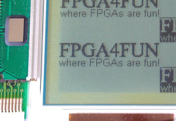
Here's a macro shot:
The drawback of rasterized bitmaps is that you require a large enough RAM to hold the state of each pixel of the bitmap. That's expensive using internal FPGA RAM, so external RAM is often used instead.
Now, let's explore more original ways to create graphics.
Curve y=F(x)
Let's say we want to display an y=F(x) waveform, like a sine.That's surprisingly easy to do. We hold the "Y" values into a blockram and generate the picture line by line by reading the RAM and comparing the values against "CounterY" (the current line number).
// We assume CounterX and CounterY are available:
//  CounterX is the pixel number of the current line
//  CounterY is the line number

// We use a RAM to hold the "Y" values
// Y=F(CounterX)
wire [7:0] RAM_Y_value;
blockram_8x512 RAM_FXY(.clk(clk), .rd_adr(CounterX), .data_out(RAM_Y_value));

// check for equality between the "Y" values and "CounterY"
reg grcpeq1;  always @(posedge clk) grcpeq1 <= (RAM_Y_value==CounterY);
reg grcpeq2;  always @(posedge clk) grcpeq2 <= grcpeq1;

// check for "greater-than" between the "Y" values and "CounterY"
reg grcp1;  always @(posedge clk) grcp1 <= (RAM_Y_value>CounterY);
reg grcp2;  always @(posedge clk) grcp2 <= grcp1;

// display a pixel if equality, or if "CounterY" is between 2 successive "Y" values
wire FXpix= grcpeq2 | (grcp1 ^ grcp2);
Here's the result using F(x)=cos(x*2*pi/480)*sin(x*2*pi/480*4):
 Small.jpg)
Rotozoom
A Rotozoom is an efficient method to display a bitmap with linear geometric distortions. In particular, that allows easy rotating and zooming of a picture.In the following implementation, we display a rotated chessboard pattern on the screen.
reg [15:0] X0, Y0, X1, Y1;

always @(posedge clk)
if(Vsync)
begin
    X0 <= 0;
    Y0 <= 0;
    X1 <= 0;
    Y1 <= 0;
end
else
if(Hsync)
begin
    X0 <= X1 - 100;
    Y0 <= Y1 + 400;
    X1 <= X1 - 100;
    Y1 <= Y1 + 400;
end
else
begin
    X0 <= X0 + 400;
    Y0 <= Y0 + 100;
end

// Display a chessboard pattern by XOR'ing the MSB of X and Y counters
// You could also display a rotozoomed bitmap by feeding X and Y to a bitmap in a RAM

wire rotozoom_pix = X0[15] ^ Y0[15];
This is simplified because the increment values are fixed (400 and 100 above). You'd want to vary them in a real implementation. By varying the coefficients, you rotate and zoom the chessboard.
Here's the result, mixed with the previous waveform:
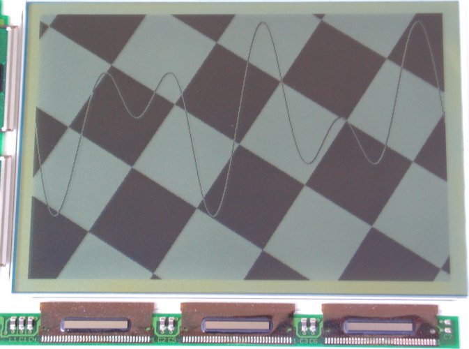
You can then mix that with some text...