

Pong game
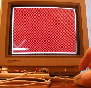
The pong game consists of a ball bouncing on a screen.
A paddle (controlled from a mouse here) enables the user to make the ball bounce back up.
Drawing a useful picture
Building up on our VGA generator, we rewrite the sync generator as an HDL module where we generate R, G and B outside.
Also the X and Y counters are more useful if they start counting from the drawing area.
The new file can be found here.
Now we can use it to draw a border around the screen.
|
module pong(clk, vga_h_sync, vga_v_sync, vga_R, vga_G, vga_B); input clk; output vga_h_sync, vga_v_sync, vga_R, vga_G, vga_B; wire inDisplayArea; wire [9:0] CounterX; wire [8:0] CounterY; hvsync_generator syncgen(.clk(clk), .vga_h_sync(vga_h_sync), .vga_v_sync(vga_v_sync), .inDisplayArea(inDisplayArea), .CounterX(CounterX), .CounterY(CounterY)); // Draw a border around the screen wire border = (CounterX[9:3]==0) || (CounterX[9:3]==79) || (CounterY[8:3]==0) || (CounterY[8:3]==59); wire R = border; wire G = border; wire B = border; reg vga_R, vga_G, vga_B; always @(posedge clk) begin vga_R <= R & inDisplayArea; vga_G <= G & inDisplayArea; vga_B <= B & inDisplayArea; end endmodule |
Drawing a paddle
Let's use a mouse to move the paddle left and right on the screen.
The quadrature decoder page shows the secret. The code is as follow:
|
reg [8:0] PaddlePosition; reg [2:0] quadAr, quadBr; always @(posedge clk) quadAr <= {quadAr[1:0], quadA}; always @(posedge clk) quadBr <= {quadBr[1:0], quadB}; always @(posedge clk) if(quadAr[2] ^ quadAr[1] ^ quadBr[2] ^ quadBr[1]) begin if(quadAr[2] ^ quadBr[1]) begin if(~&PaddlePosition) // make sure the value doesn't overflow PaddlePosition <= PaddlePosition + 1; end else begin if(|PaddlePosition) // make sure the value doesn't underflow PaddlePosition <= PaddlePosition - 1; end end |
Now that "PaddlePosition" value is known, we can display the paddle.
|
wire border = (CounterX[9:3]==0) || (CounterX[9:3]==79) || (CounterY[8:3]==0) || (CounterY[8:3]==59); wire paddle = (CounterX>=PaddlePosition+8) && (CounterX<=PaddlePosition+120) && (CounterY[8:4]==27); wire R = border | (CounterX[3] ^ CounterY[3]) | paddle; wire G = border | paddle; wire B = border | paddle; |
Drawing the ball
The ball needs to move around the screen, and bounce back when it touches an object (border or paddle).
First we display the ball. It is a square 16x16 pixels. We activate the drawing of the ball when CounterX and CounterY reach its coordinates.
|
reg [9:0] ballX; reg [8:0] ballY; reg ball_inX, ball_inY; always @(posedge clk) if(ball_inX==0) ball_inX <= (CounterX==ballX) & ball_inY; else ball_inX <= !(CounterX==ballX+16); always @(posedge clk) if(ball_inY==0) ball_inY <= (CounterY==ballY); else ball_inY <= !(CounterY==ballY+16); wire ball = ball_inX & ball_inY; |
Now for the collisions. That's the difficult part of this project.
We could check the coordinate of the ball against each object on the screen and determine if there is a collision. But that would become quickly a nightmare as the number of objects increases.
Instead we define 4 "hot-spots" pixels, one in the middle of each side of the ball. If an object (border or paddle) redraws itself at the same time that the ball draws one of its "hot-spot", we know that there is collision on that side of the ball.
|
wire border = (CounterX[9:3]==0) || (CounterX[9:3]==79) || (CounterY[8:3]==0) || (CounterY[8:3]==59); wire paddle = (CounterX>=PaddlePosition+8) && (CounterX<=PaddlePosition+120) && (CounterY[8:4]==27); wire BouncingObject = border | paddle; // active if the border or paddle is redrawing itself reg CollisionX1, CollisionX2, CollisionY1, CollisionY2; always @(posedge clk) if(BouncingObject & (CounterX==ballX ) & (CounterY==ballY+ 8)) CollisionX1<=1; always @(posedge clk) if(BouncingObject & (CounterX==ballX+16) & (CounterY==ballY+ 8)) CollisionX2<=1; always @(posedge clk) if(BouncingObject & (CounterX==ballX+ 8) & (CounterY==ballY )) CollisionY1<=1; always @(posedge clk) if(BouncingObject & (CounterX==ballX+ 8) & (CounterY==ballY+16)) CollisionY2<=1; |
(I simplified a little the above code by never resetting the collision flops, the complete code is available below).
Now we update the ball position, but only once for every video frame.
|
reg UpdateBallPosition; // active only once for every video frame always @(posedge clk) UpdateBallPosition <= (CounterY==500) & (CounterX==0); reg ball_dirX, ball_dirY; always @(posedge clk) if(UpdateBallPosition) begin if(~(CollisionX1 & CollisionX2)) // if collision on both X-sides, don't move in the X direction begin ballX <= ballX + (ball_dirX ? -1 : 1); if(CollisionX2) ball_dirX <= 1; else if(CollisionX1) ball_dirX <= 0; end if(~(CollisionY1 & CollisionY2)) // if collision on both Y-sides, don't move in the Y direction begin ballY <= ballY + (ball_dirY ? -1 : 1); if(CollisionY2) ball_dirY <= 1; else if(CollisionY1) ball_dirY <= 0; end end |
And finally we can draw all that together.
|
wire R = BouncingObject | ball | (CounterX[3] ^ CounterY[3]); wire G = BouncingObject | ball; wire B = BouncingObject | ball; reg vga_R, vga_G, vga_B; always @(posedge clk) begin vga_R <= R & inDisplayArea; vga_G <= G & inDisplayArea; vga_B <= B & inDisplayArea; end |
Whoa, wasn't so difficult after all.
The complete file is pong.zip, and works with hvsync_generator.zip
It is also possible to use HDMI to run the pong game.