

SMD (Surface Mount Device) / SMT (Surface Mount Technology)
Here's a view on common SMDs (Surface Mount Devices).
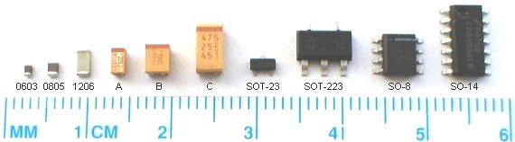
SMD resistors
SMD resistors come into several possible case sizes. Each size is described as a 4 digits number. The first 2 digits indicate the length; the last 2 indicate the width (in 0.01", or 10 mils units).For example, the three most popular sizes are:
- 0603: means 0.06"x0.03", or 60x30 mils, or 1.6x0.8mm
- 0805: means 0.08"x0.05", or 80x50 mils, or 2.0x1.25mm
- 1206: means 0.12"x0.06", or 120x60 mils, or 3.2x1.6mm
SMD capacitors
Capacitors from 1pF to 1uF are available in the same sizes, 0603 to 1206.The most popular technology is ceramic.
SMD Tantalum capacitors
Tantalum is the technology of choice for capacitors 1uF and higher.Case sizes are indicated by a letter from "A" to "E".
| Case | L x W x H (mm) |
| A | 3.2x1.6x1.6 |
| B | 3.5x2.8x1.9 |
| C | 6.0x3.2x2.5 |
| D | 7.3x4.3x2.8 |
| E | 7.3x6.0x3.6 |
Tantalum capacitors are polarized; a bar on the case indicates the positive side.
SMD transistors
The most popular size for small-signal transistor is called "SOT-23".The second most popular is "SOT-223".
SMD Integrated Circuits ("ICs")
The two most popular sizes are "SO-8" and "SO-14" (also named "SOIC-8" and "SOIC-16").SMD FPGAs
Nowadays, there are three popular packages:- TQFP (Thin Quad Flat Pack), 100 or 144 pins.
- PQFP (Plastic Quad Flat Pack), 208 or 240 pins.
- BGA (Ball-Grid Array), 256 to 1000+ pins.
SMD QFPs
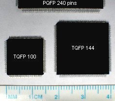
TQFPs 100 pins and 144 pins are reasonably easy to solder manually, because the pins are sturdy.
PQFPs 208 pins and 240 pins are not as easy because the pins bend very easily.
Pins are separated by 0.5mm.
See below for tutorials and links about soldering these components.
SMD BGAs
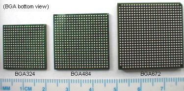
The bottom of a BGA component is actually a circuit board, with pads covered by solder balls (that's what you can see on the above picture).
The BGA balls are not made of solid metal but of solder. During board assembly, the BGA goes through an oven, melting the balls between the BGA circuit board and the application circuit board.
Balls are commonly separated by 1mm or 1.27mm, less often by 0.8mm.
How to solder SMDs
You need the following equipment:- A temperature-regulated ("thermo-regulated") solder iron with a small tip.
- A flux dispenser, in bottle or pen form.
- Tweezers, to hold the components while soldering them.
- Solderwick, to clean up excess solder.
- A temperature-regulated solder iron stays at a constant temperature, no matter if used to solder light or heavy loads. That's different than a simpler (and cheaper) power-regulated iron. A power-regulated iron might get too hot when not in used, and too cold when in heavy use.
- Flux is essential to solder SMDs. Most solder contain a flux core already, which may have been adequate for yesterday's soldering jobs, but SMD soldering requires additional source of flux to get good soldering quality. The flux is used to reduce the oxidation of the solder (happens very quickly at soldering temperatures). It allows the solder to flow easily and make good solder joins.
Links
- A guide for SMD repairs
- A Surface Mount Soldering Procedure
- Using solder paste in Have you seen my new soldering Iron?, from the Seattle Robotics Society
- An illustrated SMD Soldering Guide by Infidigm