Graphic LCD panel 4 - Text
Let's try to display characters on our panel.
This way, the panel can be used as a text terminal.
Our 480x320 sample panel can be used as an 80-column x 40-line console (using a 6x8 character font) or a 60-column x 40-line console (using an 8x8 character font).
We are going to use a "character generator" technique.
Character generator
Let's assume the word "Hello" is somewhere on the screen. In ASCII, that uses 5 bytes (0x48, 0x65, 0x6C, 0x6C, 0x6F). Our simple character generator uses one RAM to hold the characters to display, and one ROM to hold the font.
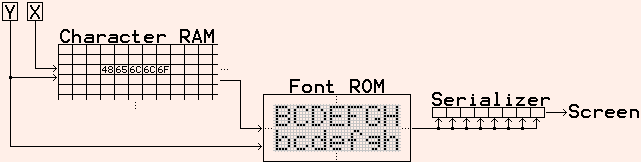
"Font ROM" contains the representation of each possible character. Here are sample sets:
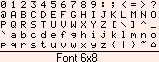
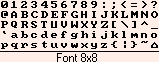
Changing the content of the "Character RAM" makes characters appear on the panel.
8x8 font implementation
On the panel, a 6x8 font looks somewhat nicer than an 8x8 font, but 8x8 is easier to implement, so that's what we try first.
By using a 2KB RAM for the "Character RAM", we can have 32 lines of 64 characters... so 5 bits to count the lines and 6 bits to count the columns.
By keeping all the numbers a power of two, the implementation stays as simple as possible.
Here's what we got:
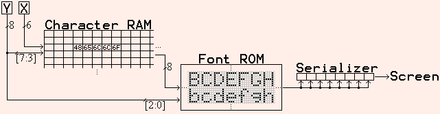
We use 6 bits from CounterX, and 8 bits from CounterY (5 bits for the "Character RAM", plus 3 bits for the "Font ROM"). "Font ROM" uses a total of 11 bits.
The design goes as follows:
wire [7:0] CharacterRAM_dout;

ram8x2048 CharacterRAM(
	.clk(clk),
	.rd_adr({CounterY[7:3],CounterX[6:1]}),
	.data_out(CharacterRAM_dout)
);

wire [7:0] raster8;
rom8x2048 FontROM(
	.clk(clk),
	.rd_adr({CharacterRAM_dout, CounterY[2:0]}),
	.data_out(raster8)
);

wire [3:0] LCDdata = CounterX[0] ? raster8[7:4] : raster8[3:0];
A few details:
- Because my LCD panel takes 4 pixels per clock, we need 2 clocks for 1 character width (1 character width=8 pixels). That's why "Character RAM" uses "CounterX[6:1]" instead of "CounterX[5:0]" above.
- In an FPGA, it makes sense that the "Font ROM" is actually a RAM. This way, the font can be loaded or changed at runtime.
- The mechanism to write the RAMs is not shown above.
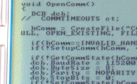
Here's a shot of the LCD with an 8x8 font:
6x8 font implementation
The 6x8 font allows for more characters to be displayed (and looks better on the panel too!). My particular panel width is 480 pixels, which translates conveniently into 80 columns.
The 6x8 font is more complicated to handle than 8x8 because the font width (6) is not a power of 2.
That means we don't display the same part of a character at each clock cycle anymore.
- With CounterX=0, we display the first 4 pixels of CHAR[0]
- With CounterX=1, we display the last 2 pixels of CHAR[0] and the first 2 pixels of CHAR[1]
- With CounterX=2, we display the last 4 pixels of CHAR[1]
- With CounterX=3, we display the first 4 pixels of CHAR[2]
- With CounterX=4, we display the last 2 pixels of CHAR[2] and the first 2 pixels of CHAR[3]
- ...
That is done using a simple case statement
wire [3:0] charfont0, charfont1;

always @(posedge clk)
begin
  case(cnt_mod3)
    2'b00: LCDdata <=  charfont0;
    2'b01: LCDdata <= {charfont0[3:2], charfont1[3:2]};
    2'b10: LCDdata <= {charfont1[3:2], charfont0[1:0]};
  endcase
end
with a modulus-3 counter (it counts 0, 1, 2, 0, 1, 2, 0, 1, ...)
reg [1:0] cnt_mod3;
always @(posedge clk) if(cnt_mod3==2) cnt_mod3 <= 0; else cnt_mod3 <= cnt_mod3 + 1;
but we also need a character-counter for the "Character RAM"
// character-counter (increments only twice every 3 clocks)
reg [6:0] cnt_charbuf;
always @(posedge clk) if(cnt_mod3!=1) cnt_charbuf <= cnt_charbuf + 1;

wire [11:0] CharacterRAM_rdaddr = CounterY[8:3]*80 + cnt_charbuf;
wire [7:0] CharacterRAM_dout;

// 80 columns x 40 lines = 3200 characters, so we need a 4KB RAM this time
ram8x4096 CharacterRAM(
	.clk(clk),
	.rd_adr(CharacterRAM_rdaddr),
	.data_out(CharacterRAM_dout)
);
and two "Font ROMs".
// remember the previous character displayed
reg [7:0] CharacterRAM_dout_last;
always @(posedge clk) CharacterRAM_dout_last <= CharacterRAM_dout;

// because we need it when we display 2 half characters at once
wire [10:0] readaddr0 = {CharacterRAM_dout, CounterY[2:0]};
wire [10:0] readaddr1 = {CharacterRAM_dout_last, CounterY[2:0]};

// The font ROMs are split in two blockrams, holding 4 pixels each
// (half of the second ROM is not used, since we need only 6 pixels)
rom4x2048 FontROM0(.clk(clk), .rd_adr(readaddr0), .data_out(charfont0));
rom4x2048 FontROM1(.clk(clk), .rd_adr(readaddr1), .data_out(charfont1));
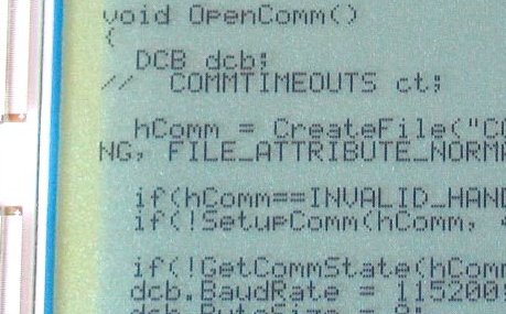
Here's a shot of the LCD with a 6x8 font:
Hardware cursor
Let's implement a blinking cursor that can be placed on any character on the panel.
First we use a video-frame counter to "time" the blinking. Using 6 bits, the cursor blinks every 64 frames.
reg [5:0] cnt_cursorblink;
always @(posedge clk) if(VSync & HSync) cnt_cursorblink <= cnt_cursorblink + 1;
wire cursorblinkstate = cnt_cursorblink[5];  // cursor on for 32 frames, off for 32 frames
Now let's assume the cursor address position is available in a "CursorAddress" register.
// Do we have a cursor-character match?
wire cursorblink_adrmatch = cursorblinkstate & (CharacterRAM_rdaddr==CursorAddress);

// When we have a match, "invert" the character
// First for charfont0
wire [3:0] charfont0_cursor = charfont0 ^ {4{cursorblink_adrmatch}};

// Next for charfont1
reg cursorblink_adrmatch_last;
always @(posedge clk) cursorblink_adrmatch_last <= cursorblink_adrmatch;
wire [3:0] charfont1_cursor = charfont1 ^ {4{cursorblink_adrmatch_last}};
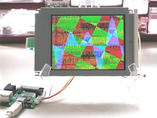
Whoa, we can display graphics and text!
All this is applicable to monochrome and color LCDs.
Here's what happens when we get carried away on a color LCD...
Your turn to experiment!
Links
- The default Text LCD modules character font.
- A VGA Video Signal Generation document.