

Serial interface 1 - How the RS-232 serial interface works
An RS-232 interface has the following characteristics:
- Uses a 9 pins connector "DB-9" (older PCs use 25 pins "DB-25").
- Allows bidirectional full-duplex communication (the PC can send and receive data at the same time).
- Can communicate at a maximum speed of roughly 10KBytes/s.
DB-9 connector
You probably already saw this connector on the back of your PC.
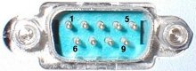
It has 9 pins, but the 3 important ones are:
- pin 2: RxD (receive data).
- pin 3: TxD (transmit data).
- pin 5: GND (ground).
Using just 3 wires, you can send and receive data.
Data is commonly sent by chunks of 8 bits (we call that a byte) and is "serialized": the LSB (data bit 0) is sent first, then bit 1, ... and the MSB (bit 7) last.
Asynchronous communication
This interface uses an asynchronous protocol. That means that no clock signal is transmitted along the data. The receiver has to have a way to "time" itself to the incoming data bits.
In the case of RS-232, that's done this way:
- Both side of the cable agree in advance on the communication parameters (speed, format...). That's done manually before communication starts.
- The transmitter sends "idle" (="1") when and as long as the line is idle.
- The transmitter sends "start" (="0") before each byte transmitted, so that the receiver can figure out that a byte is coming.
- The 8 bits of the byte data are sent.
- The transmitter sends "stop" (="1") after each byte.
Let's see how looks the byte 0x55 when transmitted:
Byte 0x55 is 01010101 in binary.
But since it is transmitted LSB (bit-0) first, the line toggles like that: 1-0-1-0-1-0-1-0.
Here's another example:
Here the data is 0xC4, can you see it?
The bits are harder to see.
That illustrates how important it is for the receiver to know at which speed the data is sent.
How fast can we send data?
The speed is specified in baud, i.e. how many bits-per-seconds can be sent. For example, 1000 bauds would mean 1000 bits-per-seconds, or that each bit lasts one millisecond.
Common implementations of the RS-232 interface (like the one used in PCs) don't allow just any speed to be used. If you want to use 123456 bauds, you're out of luck. You have to settle to some "standard" speed. Common values are:
- 1200 bauds.
- 9600 bauds.
- 38400 bauds.
- 115200 bauds (usually the fastest you can go).
At 115200 bauds, each bit lasts (1/115200) = 8.7µs. If you transmit 8-bits data, that lasts 8 x 8.7µs = 69µs. But each byte requires an extra start and stop bit, so you actually need 10 x 8.7µs = 87µs. That translates to a maximum speed of 11.5KBytes per second.
At 115200 bauds, some PCs with buggy chips require a "long" stop bit (1.5 or 2 bits long...) which make the maximum speed drop to around 10.5KBytes per second.
Physical layer
The signals on the wires use a positive/negative voltage scheme.
- "1" is sent using -10V (or between -5V and -15V).
- "0" is sent using +10V (or between 5V and 15V).
So an idle line carries something like -10V.
Links
- An Introduction to RS232 Serial Communications
- Voltage Waveshapes, part of this huge Serial HOWTO