

Opto 1 - How LEDs work
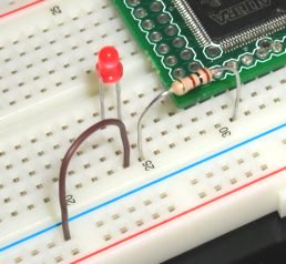
Controlling an LED with an FPGA
The ideal LED control is a current source.
FPGA pins are voltage controlled, so a simple solution is to add a resistor in series with the LED.
Values from 100Ω to 1KΩ are common.
LED electronic basics
An LED (Light Emitting Diode) is a semiconductor device that produces light when current is going through it.The LED symbol looks like a diode, with an anode (+) and cathode (-).

- An LED acts like a diode - conducts electricity one way, blocks it the other way.
- Like all diodes, it has a threshold voltage. The threshold voltage of a common red LED is around 2.0V.
- Below 2.0V, no light is emitted (no current goes through the LED).
- Above 2.0V, the LED conducts electricity, and the light intensity depends of the current that goes through the LED.
- An LED has two physical limits not to exceed:
- A maximum forward current (and so a maximum light intensity). The maximum is typically a few 10's of mA.
- A maximum reverse voltage (even though no current goes through when the LED is reversed biased, do not reverse bias it too much). The reverse voltage limit is typically 5V... much lower than common diodes!