

JTAG 4 - Run a boundary-scan
Now let's ask the TAP controllers to go into boundary-scan mode, where the DR chain goes through each IO block and can read or hijack each pin!
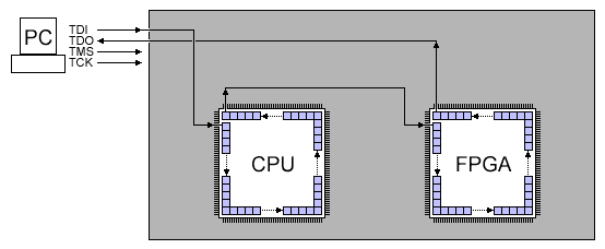
Boundary-scan can be used even while a device is otherwise running. So for example, using JTAG on an FPGA, you can tell the status of each pin while the FPGA is running.
SAMPLE
Let's try to read the value of the pins. We use a JTAG instruction called SAMPLE for that. Each IC instruction code list is different. You have to look into the IC datasheet, or the IC BSDL file to get the codes.
A BSDL file is actually a VHDL file that describes the boundary chain of an IC.
Here's an interesting portion of an Altera BSDL file (Cyclone EP1C3 in TQFP 100 pins package).
attribute INSTRUCTION_LENGTH of EP1C3T100 : entity is 10;

attribute INSTRUCTION_OPCODE of EP1C3T100 : entity is
  "BYPASS            (1111111111), "&
  "EXTEST            (0000000000), "&
  "SAMPLE            (0000000101), "&
  "IDCODE            (0000000110), "&
  "USERCODE          (0000000111), "&
  "CLAMP             (0000001010), "&
  "HIGHZ             (0000001011), "&
  "CONFIG_IO            (0000001101)";

attribute INSTRUCTION_CAPTURE of EP1C3T100 : entity is "0101010101";

attribute IDCODE_REGISTER of EP1C3T100 : entity is
  "0000"&               --4-bit Version
  "0010000010000001"&   --16-bit Part Number (hex 2081)
  "00001101110"&        --11-bit Manufacturer's Identity
  "1";                  --Mandatory LSB

attribute BOUNDARY_LENGTH of EP1C3T100 : entity is 339;
Here's what we learn from this device's BSDL:
- The length of the IR register (10 bits long).
- The list of possible IR instructions, with their 10 bits codes. The code for SAMPLE is 0000000101b = 0x005.
- The IDCODE of the part (the manufacturer code reads 00001101110b = 0x6E, which is Altera. Xilinx would have been 00001001001b = 0x49).
- The length of the boundary-scan chain (339 bits long).
The boundary-scan is 339 bits long.
That doesn't mean there are 339 pins.
Each pin use an IO pad on the IC die.
Some IO pads use one, two or three bits from the chain (depending if the pin is input only, output with tri-state, or both).
See the links at the bottom of this page for more details.
Also some registers correspond to IO pads that may not be bounded (they exist on the IC die but are not accessible externally).
Which explains why a 100-pin device can have a 339-bit boundary-scan chain.
Going back to the BSDL file, we also get this:
attribute BOUNDARY_REGISTER of EP1C3T100 : entity is
  --BSC group 0 for I/O pin 100
  "0   (BC_1, IO100, input, X)," &
  "1   (BC_1, *, control, 1)," &
  "2   (BC_1, IO100, output3, X, 1, 1, Z)," &

  --BSC group 1 for I/O pin 99
  "3   (BC_1, IO99, input, X)," &
  "4   (BC_1, *, control, 1)," &
  "5   (BC_1, IO99, output3, X, 4, 1, Z)," &

  ...
  ...
  ...

  --BSC group 112 for I/O pin 1
  "336 (BC_1, IO1, input, X)," &
  "337 (BC_1, *, control, 1)," &
  "338 (BC_1, IO1, output3, X, 337, 1, Z)" ;
This lists all the 339 bits of the chain, and what they do.
For example, bit 3 is the one that tells us what is the value of pin 99.
Let's read the boundary-scan registers, and print the value of pin 99:
  // go to reset state
  for(i=0; i<5; i++) JTAG_clock(TMS);

  // go to Shift-IR
  JTAG_clock(0);
  JTAG_clock(TMS);
  JTAG_clock(TMS);
  JTAG_clock(0);
  JTAG_clock(0);

  // Assuming that IR is 10 bits long,
  // that there is only one device in the chain,
  // and that SAMPLE code = 0000000101b
  JTAG_clock(1);
  JTAG_clock(0);
  JTAG_clock(1);
  JTAG_clock(0);
  JTAG_clock(0);
  JTAG_clock(0);
  JTAG_clock(0);
  JTAG_clock(0);
  JTAG_clock(0);
  JTAG_clock(0 or TMS);  // last bit needs to have TMS active, to exit shift-IR

  // we are in Exit1-IR, go to Shift-DR
  JTAG_clock(TMS);
  JTAG_clock(TMS);
  JTAG_clock(0);
  JTAG_clock(0);

  // read the boundary-scan chain bits in an array called BSB
  JTAG_read(BSB, 339);
  printf("Status of pin 99 = %d\n, BSB[3]);
Easy, right?
Do more with JTAG
- JTAG can hijack the pins. The JTAG instruction for that is EXTEST ("external test").
- JTAG can perform FPGA configuration. See for example this file.
- JTAG can be used as debug port - for example Altera's SignalTap and Xilinx's ChipScope.
Your turn to experiment!
Links
- Boundary-Scan Testing in Altera Devices.
- Xilinx BSDL files.
- Altera BSDL files.