

10BASE-T FPGA interface 0 - A recipe to send Ethernet traffic
Here we demonstrate how to send Ethernet traffic directly from an FPGA to a PC.
For this recipe, you'll need:- An FPGA development board, with 2 free IOs and a 20MHz clock.
- A PC with an Ethernet card, and the TCP-IP stack installed (if you can browse the Internet, you're good).
- Optionally, a network hub or switch.
1. Connect the FPGA board to the Ethernet network
Here's a view of a typical test setup, using an Ethernet hub or switch.
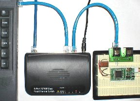
Using a hub or switch allows the PC to stay connected to your regular network (if you have one) while doing this experiment.
But you can also connect the FPGA directly to the PC.
We are using a Pluto board here with an external 20MHz oscillator.
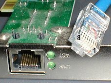
Connect two IOs from the FPGA board to an Ethernet cable.
- If the cable's other end connects to a hub or switch (like on the picture above), use pin 1 and 2 of the Ethernet cable.
- If the cable's other end connects directly to the PC, use pin 3 and 6.
For the pin numbers, get help from this picture:
Note that the polarity usually doesn't matter, because the signal is differential and Ethernet equipment can detect the polarity from the incoming signal.
Also even if that works in practice, we are not compliant to the Ethernet electrical requirements by just connecting the FPGA to a cable (we would need a filter and a transformer).
So let's just consider that a "lab" experiment.
2. Get the network info from the PC
Type "ipconfig /all" on the command-line.
Write down your "Physical Address" and your "IP Address".
3. Program the FPGA
Compile the following Verilog HDL code.
Make sure to:
- Update the data values ("IP source", "IP destination" and "Physical Address") in the code.
- Do the correct pin assignment for your board (there are just 3 pins used!).
|
module TENBASET_TxD(clk20, Ethernet_TDp, Ethernet_TDm); // a 20MHz clock (this code won't work with a different frequency) input clk20; // the two differential 10BASE-T outputs output Ethernet_TDp, Ethernet_TDm; // "IP source" - put an unused IP - if unsure, see comment below after the source code parameter IPsource_1 = 192; parameter IPsource_2 = 168; parameter IPsource_3 = 0; parameter IPsource_4 = 44; // "IP destination" - put the IP of the PC you want to send to parameter IPdestination_1 = 192; parameter IPdestination_2 = 168; parameter IPdestination_3 = 0; parameter IPdestination_4 = 2; // "Physical Address" - put the address of the PC you want to send to parameter PhysicalAddress_1 = 8'h00; parameter PhysicalAddress_2 = 8'h07; parameter PhysicalAddress_3 = 8'h95; parameter PhysicalAddress_4 = 8'h0B; parameter PhysicalAddress_5 = 8'hFB; parameter PhysicalAddress_6 = 8'hAF; ////////////////////////////////////////////////////////////////////// // sends a packet roughly every second reg [23:0] counter; always @(posedge clk20) counter<=counter+1; reg StartSending; always @(posedge clk20) StartSending<=&counter; ////////////////////////////////////////////////////////////////////// // we send a UDP packet, 18 bytes payload // calculate the IP checksum, big-endian style parameter IPchecksum1 = 32'h0000C53F + (IPsource_1<<8)+IPsource_2+(IPsource_3<<8)+IPsource_4+ (IPdestination_1<<8)+IPdestination_2+(IPdestination_3<<8)+(IPdestination_4); parameter IPchecksum2 = ((IPchecksum1&32'h0000FFFF)+(IPchecksum1>>16)); parameter IPchecksum3 = ~((IPchecksum2&32'h0000FFFF)+(IPchecksum2>>16)); reg [6:0] rdaddress; reg [7:0] pkt_data; always @(posedge clk20) case(rdaddress) // Ethernet preamble 7'h00: pkt_data <= 8'h55; 7'h01: pkt_data <= 8'h55; 7'h02: pkt_data <= 8'h55; 7'h03: pkt_data <= 8'h55; 7'h04: pkt_data <= 8'h55; 7'h05: pkt_data <= 8'h55; 7'h06: pkt_data <= 8'h55; 7'h07: pkt_data <= 8'hD5; // Ethernet header 7'h08: pkt_data <= PhysicalAddress_1; 7'h09: pkt_data <= PhysicalAddress_2; 7'h0A: pkt_data <= PhysicalAddress_3; 7'h0B: pkt_data <= PhysicalAddress_4; 7'h0C: pkt_data <= PhysicalAddress_5; 7'h0D: pkt_data <= PhysicalAddress_6; 7'h0E: pkt_data <= 8'h00; 7'h0F: pkt_data <= 8'h12; 7'h10: pkt_data <= 8'h34; 7'h11: pkt_data <= 8'h56; 7'h12: pkt_data <= 8'h78; 7'h13: pkt_data <= 8'h90; // IP header 7'h14: pkt_data <= 8'h08; 7'h15: pkt_data <= 8'h00; 7'h16: pkt_data <= 8'h45; 7'h17: pkt_data <= 8'h00; 7'h18: pkt_data <= 8'h00; 7'h19: pkt_data <= 8'h2E; 7'h1A: pkt_data <= 8'h00; 7'h1B: pkt_data <= 8'h00; 7'h1C: pkt_data <= 8'h00; 7'h1D: pkt_data <= 8'h00; 7'h1E: pkt_data <= 8'h80; 7'h1F: pkt_data <= 8'h11; 7'h20: pkt_data <= IPchecksum3[15:8]; 7'h21: pkt_data <= IPchecksum3[ 7:0]; 7'h22: pkt_data <= IPsource_1; 7'h23: pkt_data <= IPsource_2; 7'h24: pkt_data <= IPsource_3; 7'h25: pkt_data <= IPsource_4; 7'h26: pkt_data <= IPdestination_1; 7'h27: pkt_data <= IPdestination_2; 7'h28: pkt_data <= IPdestination_3; 7'h29: pkt_data <= IPdestination_4; // UDP header 7'h2A: pkt_data <= 8'h04; 7'h2B: pkt_data <= 8'h00; 7'h2C: pkt_data <= 8'h04; 7'h2D: pkt_data <= 8'h00; 7'h2E: pkt_data <= 8'h00; 7'h2F: pkt_data <= 8'h1A; 7'h30: pkt_data <= 8'h00; 7'h31: pkt_data <= 8'h00; // payload 7'h32: pkt_data <= 8'h00; // put here the data that you want to send 7'h33: pkt_data <= 8'h01; // put here the data that you want to send 7'h34: pkt_data <= 8'h02; // put here the data that you want to send 7'h35: pkt_data <= 8'h03; // put here the data that you want to send 7'h36: pkt_data <= 8'h04; // put here the data that you want to send 7'h37: pkt_data <= 8'h05; // put here the data that you want to send 7'h38: pkt_data <= 8'h06; // put here the data that you want to send 7'h39: pkt_data <= 8'h07; // put here the data that you want to send 7'h3A: pkt_data <= 8'h08; // put here the data that you want to send 7'h3B: pkt_data <= 8'h09; // put here the data that you want to send 7'h3C: pkt_data <= 8'h0A; // put here the data that you want to send 7'h3D: pkt_data <= 8'h0B; // put here the data that you want to send 7'h3E: pkt_data <= 8'h0C; // put here the data that you want to send 7'h3F: pkt_data <= 8'h0D; // put here the data that you want to send 7'h40: pkt_data <= 8'h0E; // put here the data that you want to send 7'h41: pkt_data <= 8'h0F; // put here the data that you want to send 7'h42: pkt_data <= 8'h10; // put here the data that you want to send 7'h43: pkt_data <= 8'h11; // put here the data that you want to send default: pkt_data <= 8'h00; endcase ////////////////////////////////////////////////////////////////////// // and finally the 10BASE-T's magic reg [3:0] ShiftCount; reg SendingPacket; always @(posedge clk20) if(StartSending) SendingPacket<=1; else if(ShiftCount==14 && rdaddress==7'h48) SendingPacket<=0; always @(posedge clk20) ShiftCount <= SendingPacket ? ShiftCount+1 : 15; wire readram = (ShiftCount==15); always @(posedge clk20) if(ShiftCount==15) rdaddress <= SendingPacket ? rdaddress+1 : 0; reg [7:0] ShiftData; always @(posedge clk20) if(ShiftCount[0]) ShiftData <= readram ? pkt_data : {1'b0, ShiftData[7:1]}; // generate the CRC32 reg [31:0] CRC; reg CRCflush; always @(posedge clk20) if(CRCflush) CRCflush <= SendingPacket; else if(readram) CRCflush <= (rdaddress==7'h44); reg CRCinit; always @(posedge clk20) if(readram) CRCinit <= (rdaddress==7); wire CRCinput = CRCflush ? 0 : (ShiftData[0] ^ CRC[31]); always @(posedge clk20) if(ShiftCount[0]) CRC <= CRCinit ? ~0 : ({CRC[30:0],1'b0} ^ ({32{CRCinput}} & 32'h04C11DB7)); // generate the NLP reg [17:0] LinkPulseCount; always @(posedge clk20) LinkPulseCount <= SendingPacket ? 0 : LinkPulseCount+1; reg LinkPulse; always @(posedge clk20) LinkPulse <= &LinkPulseCount[17:1]; // TP_IDL, shift-register and manchester encoder reg SendingPacketData; always @(posedge clk20) SendingPacketData <= SendingPacket; reg [2:0] idlecount; always @(posedge clk20) if(SendingPacketData) idlecount<=0; else if(~&idlecount) idlecount<=idlecount+1; wire dataout = CRCflush ? ~CRC[31] : ShiftData[0]; reg qo; always @(posedge clk20) qo <= SendingPacketData ? ~dataout^ShiftCount[0] : 1; reg qoe; always @(posedge clk20) qoe <= SendingPacketData | LinkPulse | (idlecount<6); reg Ethernet_TDp; always @(posedge clk20) Ethernet_TDp <= (qoe ? qo : 1'b0); reg Ethernet_TDm; always @(posedge clk20) Ethernet_TDm <= (qoe ? ~qo : 1'b0); endmodule |
About the "IP source" that you have to choose in the code above, pick something that is compatible with your network, but still unused.
The example network shown above have IPs starting with "192.168.0" (the PC IP is 192.168.0.2 with a mask of 255.255.255.0).
So here IPs like 192.168.0.x can be used.
To check if an IP is used or not, "ping" it.
4. Incoming packets
Run this UDP receiver software on the PC (source code included).
You get something like this:
Send useful traffic
The code above sends 18 data bytes in each UDP packets. The 18 bytes can come from anywhere, so for example, you can modify the code to send the value of FPGA pins.
Have fun sending UDP packets!