

VGA
FPGAs can easily become video generators.
Driving a VGA monitor
A VGA monitor requires 5 signals to display a picture.
- R, G and B (red, green and blue signals).
- HS and VS (horizontal and vertical synchronization).
The R, G and B are analog signals, while HS and VS are digital signals.
Creating a VGA signal from FPGA pins
Here's how to drive the VGA connector:
- Pins 13 and 14 of the VGA connector (HS and VS) are digital signals, so can be driven directly from two FPGA pins (or through low value resistors, like 100Ω).
- Pins 1, 2 and 3 (R, G and B) are 75Ω analog signals with nominal values of 0.7V. With 3.3V FPGA outputs, use three 270Ω series resistors. The resistors form voltage dividers with the 75Ω resistors in the monitor inputs so that 3.3V become 3.3*75/(270+75)=0.72V, pretty close to 0.7V. Driving these RGB pins with different combinations of 0's and 1's gives us up to 8 colors.
- Ground pins are pins 5, 6, 7, 8 and 10.
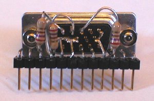
Here's a view of the female VGA connector connected to Pluto on a breadboard.
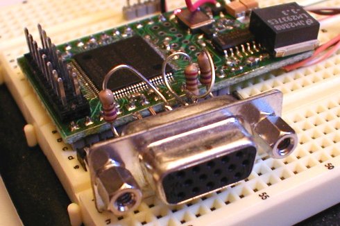
Back view of the female VGA connector to 12-pins header assembly. The 12-pins header makes it easy to connect to a breadboard. The three 270Ω series resistors are clearly visible. We could also have used an adapter board.
Frequency generator
A monitor always displays a picture line-by-line, from top-to-bottom. Each line is drawn from left-to-right.
That's hard-coded, you cannot change that.
But you specify when the drawing starts by sending short pulses on HS and VS at fixed intervals. HS makes a new line to start drawing; while VS tells that the bottom has been reached (makes the monitor go back up to the top line).
For the standard 640x480 VGA video signal, the frequencies of the pulses should be:
| Vertical Freq (VS) | Horizontal Freq (HS) |
|---|---|
| 60 Hz (=60 pulses per second) | 31.5 kHz (=31500 pulses per second) |
To create a standard video signal, there is more details to take care of, like the duration of the pulses and the relationship between HS and VS. Get an idea on this page.
A video generator
VGA monitors are usually multisync, so can accommodate non-standard frequencies - no need to generate exactly 60Hz and 31.5KHz anymore (but if you are using an older non-multisync VGA monitor, you'll need to generate the exact frequencies).
Let's start with X and Y counter.
|
reg [9:0] CounterX; reg [8:0] CounterY; wire CounterXmaxed = (CounterX==767); always @(posedge clk) if(CounterXmaxed) CounterX <= 0; else CounterX <= CounterX + 1; always @(posedge clk) if(CounterXmaxed) CounterY <= CounterY + 1; |
CounterX counts 768 values (from 0 to 767) and CounterY counts 512 values (0 to 511).
Now, CounterX is used to generate HS, and CounterY to generate VS. Using a 25MHz clock, we get 32.5KHz for HS and 63.5Hz for VS. The pulses need to be active long enough for the monitor to detect them. Let's use a 16 clocks pulse (0.64µs) for HS and a full horizontal line length pulse for VS (768 clocks or 30µs). That's shorter than what the VGA spec calls for but works fine anyway.
We "register" the HS and VS pulses (to get glitch free outputs).
|
reg vga_HS, vga_VS; always @(posedge clk) begin vga_HS <= (CounterX[9:4]==0); // active for 16 clocks vga_VS <= (CounterY==0); // active for 768 clocks end |
The VGA sync pulses need to be negative, so we invert the signals.
|
assign vga_h_sync = ~vga_HS; assign vga_v_sync = ~vga_VS; |
Finally we can drive the R, G and B signals. As a first cut, we can use some bits of the X and Y counters to get nice square color patterns...
|
assign R = CounterY[3] | (CounterX==256); assign G = (CounterX[5] ^ CounterX[6]) | (CounterX==256); assign B = CounterX[4] | (CounterX==256); |
and we get a picture on the VGA monitor!