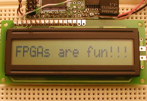
Text LCD module
Text LCD modules are cheap and easy to interface using a microcontroller or FPGA.
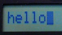
Here's a 1 line x 16 characters module:
To control an LCD module, you need 11 IO pins to drive an 8-bit data bus and 3 control signals. The 3 control signals are:
- E: enable, or "LCD-select". Active high.
- R/W: read/write. 0 to write, 1 to read.
- RS: register select, 0 for command bytes, 1 for data bytes.
Most of the LCD modules are based on the HD44780 chip or compatible. Check Wikipedia for more information.
7-bit design
Let's drive the LCD module from an FPGA board.
Here's the block diagram of our design:
Pluto receives data from the PC serial port, de-serializes it, and send it to the LCD module. The de-serializer is the same module from the serial interface project, so it is just instantiated here.
|
module LCDmodule(clk, RxD, LCD_RS, LCD_RW, LCD_E, LCD_DataBus); input clk, RxD; output LCD_RS, LCD_RW, LCD_E; output [7:0] LCD_DataBus; wire RxD_data_ready; wire [7:0] RxD_data; async_receiver deserializer(.clk(clk), .RxD(RxD), .RxD_data_ready(RxD_data_ready), .RxD_data(RxD_data)); |
Every time a byte becomes available from the serial port, then "RxD_data_ready" is active for one clock period.
The PC sends us data through the serial port in 8-bit mode. Ideally, we would need to receive 9 bits from the PC, so that we can drive the 8-bit data bus and the "RS" line of the LCD module. For now, let's use the MSB (bit 7) of the data received to drive "RS", and send only 7 bits to the data bus.
|
assign LCD_RS = RxD_data[7]; assign LCD_DataBus = {1'b0, RxD_data[6:0]}; // sends only 7 bits to the module, padded with a '0' in front to make 8 bits assign LCD_RW = 0; |
We never read from the LCD module, so the R/W line is tied to ground.
The last complication is that the "E" signal needs to be active for a long time, 220ns. That's long from the FPGA point of view, since I use a 25MHz clock (40ns period). So "E" needs to be driven for at least 5.5 clocks. Here we drive it for 7 clocks, using a counter to count the clocks.
|
reg [2:0] count; always @(posedge clk) if(RxD_data_ready | (count!=0)) count <= count + 1; |
The "E" signal is created using a register, so that it is guaranteed to be glitch-free.
|
reg LCD_E; always @(posedge clk) LCD_E <= (count!=0); |
The waveform looks like that:
The HDL design is here.
The software
We initialize the LCD and send some data to be displayed.
Here's the C code to initialize the LCD module and display 'hello'.
|
void main() { OpenComm(); // initialize the LCD module WriteCommByte(0x38); // "Function Set" in 8 bits mode WriteCommByte(0x0F); // "Display ON" with cursors ON WriteCommByte(0x01); // "Clear Display", can take up to 1.64ms, so the delay Sleep(2); // display "hello" WriteCommByte('h' + 0x80); WriteCommByte('e' + 0x80); WriteCommByte('l' + 0x80); WriteCommByte('l' + 0x80); WriteCommByte('o' + 0x80); CloseComm(); } |
The complete code is here.
To get more info about the HD44780 instruction set, check here.
8-bit design
The major drawback is the earlier design is that we send only 7 bits to the LCD data bus. That is a problem because the set DD RAM Address command of the LCD module cannot be used anymore.
One easy way around that is to use an escape character. We chose character 0x00.
The new protocol is as follow:
- To send a command byte, prefix it with 0x00.
- To send a data byte, just send it, no prefix required.
The new C code is:
|
void main() { OpenComm(); // initialize the LCD module WriteCommByte(0x00); WriteCommByte(0x38); // "Function Set" in 8-bit mode WriteCommByte(0x00); WriteCommByte(0x0F); // "Display ON" with cursors ON WriteCommByte(0x00); WriteCommByte(0x01); // "Clear Display", can take up to 1.64ms, so the delay Sleep(2); WriteCommByte('h'); WriteCommByte('e'); WriteCommByte('l'); WriteCommByte('l'); WriteCommByte('o'); WriteCommByte(0x00); WriteCommByte(0xC0); // go on second half of LCD WriteCommByte('e'); WriteCommByte('v'); WriteCommByte('e'); WriteCommByte('r'); WriteCommByte('y'); WriteCommByte('o'); WriteCommByte('n'); WriteCommByte('e'); CloseComm(); } |
The new HDL code looks like:
|
module LCDmodule(clk, RxD, LCD_RS, LCD_RW, LCD_E, LCD_DataBus); input clk, RxD; output LCD_RS, LCD_RW, LCD_E; output [7:0] LCD_DataBus; wire RxD_data_ready; wire [7:0] RxD_data; async_receiver deserialer(.clk(clk), .RxD(RxD), .RxD_data_ready(RxD_data_ready), .RxD_data(RxD_data)); assign LCD_RW = 0; assign LCD_DataBus = RxD_data; wire Received_Escape = RxD_data_ready & (RxD_data==0); wire Received_Data = RxD_data_ready & (RxD_data!=0); reg [2:0] count; always @(posedge clk) if(Received_Data | (count!=0)) count <= count + 1; // activate LCD_E for 6 clocks, so at 25MHz, that's 6x40ns=240ns reg LCD_E; always @(posedge clk) if(LCD_E==0) LCD_E <= Received_Data; else LCD_E <= (count!=6); reg LCD_instruction; always @(posedge clk) if(LCD_instruction==0) LCD_instruction <= Received_Escape; else LCD_instruction <= (count!=7); assign LCD_RS = ~LCD_instruction; endmodule |
The HD44780 specification shows that "RS" needs to be valid for 10ns after "E" goes low. So you'll note that here "E" is driven for 6 clocks only, and the "LCD_instruction" flag is reset only after clock 7, to give 25ns room.