

CNC 6 - Motion formulas
Since the FPGA motion units accept only acceleration and time numbers, the PC's job is to calculate them. It's easy to do thanks to the very simple architecture and predictability of our motion units.
A little bit of math
We can calculate the position and speed of our axes at all time, just knowing the acceleration.
Let's have the following four variables for one axis:
- p is the position
- s is the speed
- a is the acceleration
- t is the time
We also have the delta variables:
- Δp is the delta-position (for example, if position p moves from 10 to 15, Δp is 5)
- Δs is the delta-speed
- Δa is the delta-acceleration
- Δt is the delta-time
Note that this is for one axis. Each axis is independent and needs his own set of variables.
Movement formulas (discrete time)
The first formula describes how an axis behaves, starting idle, with an acceleration of 1.
Remember the table from the hardware acceleration integrator page? (here). After 5 clocks, with an acceleration of 1, the table shows that the position increased by 15.
The formula is:
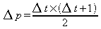
For Δt=5 (5 clocks), the formula says that the position increases by (5x6)/2=15. Good.
Note that if acceleration is bigger than 1, the result is proportional. So if acceleration is 10, position increases by 150.
The second formula describes how the system behaves at constant speed (no acceleration).

For example, if Δt=5 (5 clocks) and speed is 2, the position increases by 5x2=10. Speed is unchanged when acceleration is null.
The third formula describes how speed is affected by acceleration.

For example, if Δt=5 (5 clocks) and acceleration is 4, the speed increases by 5x4=20.
In summary, here are the two formulas that describe position and speed for a given acceleration.
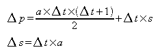
For example, if the current position is 200, speed is 10, acceleration is 2, and 5 clocks elapse, we are now at position 280 and speed 20.
Movement formulas (continuous time)
The previous formulas apply in discrete time, i.e. like in an FPGA, where everything happens on clock signals (even if the clock is very fast, it is not continuous like in the real world).
In real world, the time is continuous. Then one formula is lightly different (the +1 is missing).
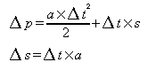
Why the +1 is missing can be puzzling. One clue is that, since the time is continuous, it is infinitely precise, and for an infinite number, adding a finite number is insignificant.
Units
If we use the metric system, we may have the following units:| Variable | Unit |
|---|---|
| p (position) | mm (millimeters) |
| s (speed) | mm/s (millimeters per second) |
| a (acceleration) | mm/s² (millimeters per second per second) |
| t (time) | s (seconds) |
In the FPGA, since we use fractional numbers with lots of bits, and high-speed calculations, the units are much smaller.
For example, if a motor step moves an axis by 0.01mm, and bit 44 of the position register moves the stepper, then the position is expressed with an accuracy of 0.01/(2^44) = 5.7e-16mm (much smaller than an atom).